


Class breaks rendering can be used to symbolize layers of types that allow configuration of symbology. This includes layers from ArcGIS Server Dynamic Map Services, tables from Spatial Data Service endpoints, and SharePoint lists. For more information on the different layer types and their capabilities, refer to the Layer Types topic.
About class breaks
Class breaks are simply categories with a minimum and maximum value. When applied to a set of data, class breaks divided the data into categories based on the value of a certain field or attribute. Since the definition of a class depends on having a minimum and maximum value, class breaks are only applicable to numeric attributes. A class breaks renderer simply maps each class to a particular symbol. Graphics with similar values for the attribute get the same symbol.
As an example, suppose you have a buildings layer with an attribute that specifies the year each building was built. You want to symbolize buildings constructed since the year 2000 in green, buildings constructed between 1980 and 2000 in yellow, and buildings built before 1980 with red. Suppose that the earliest a building was constructed in the layer is 1960. In this case, you would define classes of 1960 - 1979, 1980 - 1999, and 2000 - 2010.
Configuring a class breaks renderer
The ArcGIS Map Web Part provides a very simple experience for applying class breaks rendering to a layer. To do so, simply follow the steps below:
-
Select the layer you wish to configure class breaks for in the Map Contents panel. For instructions, see The Map Contents Panel.
-
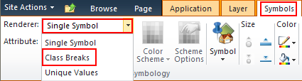
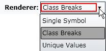
On the Symbols tab of the ribbon, expand the Renderer drop-down menu and select Class Breaks. The ArcGIS Map Web Part will automatically calculate five class breaks for the first numeric field in the layer:
-
Now that the renderer has been applied, you can configure it:
-
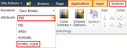
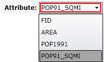
Changing the attribute - To change the field on which the symbols are based, expand the Attribute drop-down menu, then select the desired field:
-
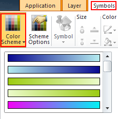
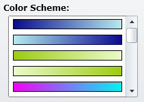
Changing the color scheme - you can apply a predefined color scheme to the renderer by expanding the Color Scheme drop-down on the ribbon and selecting the desired color scheme from the list that appears:
The color scheme is applied differently depending on the geometry type of the selected layer:
-
For a polygon layer, the colors are applied to the fill colors of the polygons.
-
For a line layer, the colors are applied to the colors of the lines.
-
For a point layer, the colors determine the color of the selected point symbol. Note that colors will not be applied to picture symbols.
-
-
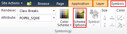
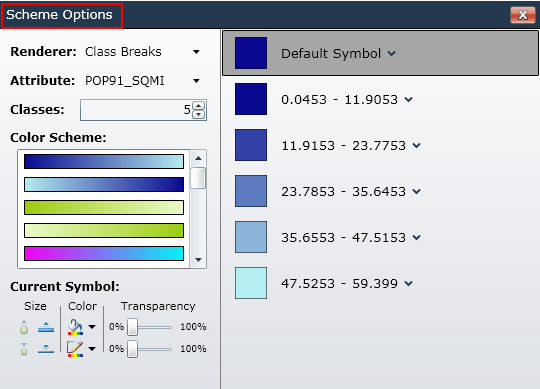
Configuring class breaks - Options for modifying class breaks are provided on the Scheme Options dialog. To open this dialog, simply click the Scheme Options button on the Symbols tab of the ribbon:
The Scheme Options dialog will be shown:
-
Changing the renderer and attribute - As with the drop-downs on the ribbon, the renderer and attribute used can also be changed by selecting items from the Renderer and Attribute drop-down menus on the dialog:
-
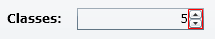
Changing the number of classes - To change the number of classes, type the desired number in the textbox next to the classes label, or use the up and down buttons next to the number:
-
Changing the color scheme - Just as you can on the ribbon, you can also select a color scheme from the Scheme Options dialog. To do so, simply select the desired scheme from the Color Scheme list:
-
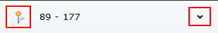
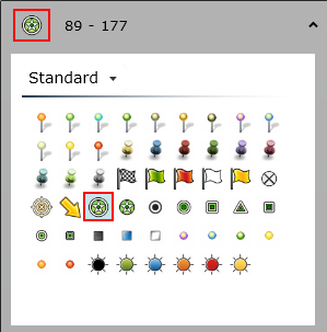
Selecting a class's symbol - To specify the symbol for one class, click the symbol to the left or the down arrow the the right of the class's value range:
Then select the desired symbol from the symbol picker:
-
Modifying a class's symbol - To modify the symbol used by a class, first select the class from the right side of the dialog. Then use the controls in the Current Symbol section of the dialog to adjust the symbol's size, color, and transparency:
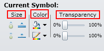
Note that the size and color controls that are enabled vary depending on the geometry type of the selected layer. For further information about specifying a symbol's size and color, refer to the Single Symbol Rendering topic
The number of Transparency sliders enabled also varies depending on the geometry type of the selected layer. For line and point layers, only one slider is enabled. In this case, the enabled slider determines the transparency of the entire symbol. For polygon layers, both sliders are enabled. The top slider determines the transparency of the symbol's fill, while the bottom slider determines the transparency of the symbol's border.
-
Changing a class's value range - The minimum and maximum values of a class can be changed by simply clicking a value and typing a new value:
-
-
 See Also
Working with layers
About Symbols