- Introduction
- Map Configuration Files
- Viewer Configuration Files
- Default.axl: A Special Viewer Configuration File
- Comparing Different CONFIG Files
Introduction
Configuration files are used to define a map. There are four types of configuration files:- A map configuration file used with Image and Feature Servers. This file is created using ArcIMS Author or an XML editor and is used as input to an ArcIMS service. The output file is in ArcXML.
- A viewer configuration file. This file is generated when a map in ArcExplorer or an ArcIMS Java Viewer is saved.
- Default.axl. This file is a special type of viewer configuration file that is generated during the ArcIMS Designer process and is used as input to the ArcIMS Java Viewers.
Note: Metadata configuration files and map configuration files created using ArcMap are not discussed in this document. Metadata configuration files are covered in Creating and Using Metadata Services. Information on creating ArcMap documents can be found in Using ArcMap.
Map Configuration Files
Map configuration files are used as input to ArcIMS services. All information in a map configuration file provides a default set of instructions for map properties and rendering. Requests can override information in the service properties, but if the request does not include any special instructions, then the default service properties prevail. The diagram below shows the flow for creating an ArcIMS service using a map configuration file as input.
|
- In Step 1, data sources are referenced and rendered. This process takes place using ArcIMS Author or by using a text or XML editor for Image and Feature Services. If non-English characters are used for layer names or font names, either ArcIMS Author or an XML editor must be used. Text editors do not display non-English characters correctly.
- In Step 2, when a session is saved in ArcIMS Author or an XML editor, the output is a map configuration file.
Note that data sources are not included in the file, only references to the data. The information in a map configuration file provides a default set of instructions for map properties and rendering. - In Step 3, the map configuration file is used as input in ArcIMS Administrator to start an Image or Feature Service.
- In Step 4, once the service has been started it runs as a process on the ArcIMS Spatial Server and is ready to receive requests.
Framework of a map configuration file
This next section focuses on the framework of ArcXML map configuration files used as input to Image and Feature MapServices. An ArcXML map configuration file can be divided into several sections. The following example shows the basic framework.Framework of a map configuration file
|
<?xml version="1.0" encoding="UTF-8"?> <ARCXML version="1.1"> <CONFIG> <ENVIRONMENT>...</ENVIRONMENT> <MAP> <PROPERTIES>...</PROPERTIES> <WORKSPACES>...</WORKSPACES> <LAYER>...</LAYER> </MAP> </CONFIG> </ARCXML> |
A map configuration file includes:
- A prolog, which is used to define the XML version and encoding.
- An ARCXML element, which is used in all ArcXML statements.
- A CONFIG element, which is used in all configuration files.
- An ENVIRONMENT element, which is used to define the locale.
- A MAP element, which is used to define the map.
ARCXML and the prolog
The first line of an ArcXML statement is the prolog. All ArcXML 1.1 statements are required to use a standard prolog that includes the XML version and encoding. The XML version is 1.0. Encoding in ArcXML 1.1 is UTF-8. UTF-16 is not supported, and responses are returned with "??" with no error messages generated.After the prolog, all ArcXML statements begin and end with ARCXML. This element is required, and the version number is 1.1.
Prolog and ARCXML
|
<?xml version="1.0" encoding="UTF-8"?> <ARCXML version="1.1"> ... </ARCXML> |
CONFIG, ENVIRONMENT, and MAP
A map configuration file distinguishes itself from a REQUEST or RESPONSE by the CONFIG element. For more information on the relationship between map configuration files, requests, and responses, see Introduction to ArcXML.The only CONFIG child elements in a map configuration file are ENVIRONMENT and MAP.
CONFIG, ENVIRONMENT, and MAP
|
<?xml version="1.0" encoding="UTF-8"?> <ARCXML version="1.1"> <CONFIG> <ENVIRONMENT>...</ENVIRONMENT> <MAP>...</MAP> </CONFIG> </ARCXML> |
ENVIRONMENT is used to set up information about the environment used in the ArcIMS service. Once the environment is established, clients in one locale can access a service created in another locale.
ENVIRONMENT and its child elements
|
<ENVIRONMENT> <LOCALE language="en" country="US" /> <UIFONT name="Arial" color="0,0,0" size="12" style="regular" /> <SEPARATORS cs=" " ts=";"/> <SCREEN dpi="96"/> </ENVIRONMENT> |
Child elements of ENVIRONMENT include the following:
- LOCALE. (Required) LOCALE is used to set the country and language for the locale of the ArcIMS site. This information is based on settings in the operating system. For example, in the United States, the country is "US" and the language is "en". Some characteristics of the United States locale include using English alphabetic characters and a decimal point (.) to represent number fractions such as 123.456.
In Germany, the country is "DE" and the language is "de". Some characteristics of the German locale include using non-English characters and a comma (,) to represent number fractions such as 123,456.
The information in LOCALE is used by the ArcIMS Java clients to determine the local environment of your ArcIMS site. Although this information is included in the map configuration file, it is not used by the ArcIMS Spatial Server. Changing the attribute values will not change the locale of the Spatial Server.
- UIFONT. (Required) UIFONT is used to set a default font for the dialogs in ArcExplorer and the ArcIMS Java Viewers.
- SEPARATORS. (Optional) SEPARATORS is used to denote characters to separate x,y coordinates and coordinate pairs. By default, x,y coordinates are separated by a space and coordinate pairs are separated by a semicolon (;). These can be changed using SEPARATORS. The attribute cs is the coordinate separator and is used to separate an x-coordinate from a y-coordinate. The attribute ts is the tuple separator and is used to separate x,y coordinate pairs.
- SCREEN. (Optional) SCREEN is used to set the resolution of the screen for the computer generating the map configuration file. This value is important for computing scale dependencies. By default, the dots per inch (dpi) is assumed to be 96 dpi. This is the value for machines with a display size set to 1024 x 768 pixels.
MAP and its child elements
|
<MAP> <PROPERTIES>...</PROPERTIES> <WORKSPACES>...</WORKSPACES> <LAYER>...</LAYER> </MAP> |
- PROPERTIES. The PROPERTIES section includes the initial map extent, map units, and current projection, as well as additional instructions used for Image Services.
- WORKSPACES. The WORKSPACES section includes the location of all the data used to create map layers.
- LAYER. One LAYER element is used for each layer in a map. LAYER contains the information about how the data should be symbolized.
MAP: PROPERTIES
PROPERTIES provides the framework for defining properties about an ArcIMS service. The child element ENVELOPE is required but all other child elements are optional. It is highly recommended to include FEATURECOORDSYS and FILTERCOORDSYS to identify the projection of the service. The child elements shown in the following example are used in both Image and Feature Services.PROPERTIES and its child elements for both Feature and Image Services
|
<PROPERTIES> <ENVELOPE minx="-105.594842" miny="-49.955227" maxx="75.672764" maxy="83.596039" name="Initial_Extent" /> <MAPUNITS units="decimal_degrees" /> <FEATURECOORDSYS id="4326" /> <FILTERCOORDSYS id="4326" /> </PROPERTIES> |
- ENVELOPE. In a map configuration file, ENVELOPE defines the extent for display. The extent is made up of a rectangle bounded by minimum and maximum x,y coordinates.
Using ENVELOPE<PROPERTIES>
<ENVELOPE minx="-128.1" miny="18.7" maxx="-53.7" maxy="51.3" name="Initial_Extent"/>
...
<PROPERTIES>
Two types of extents can be used in a map configuration file:- Intial extent: the full extent drawn when a file is first accessed.
- Extent limit: the maximum zoom limit of the map.
In the next example, both "Initial_Extent" and "Extent_Limit" are included using the attribute name.
Using Initial Extent and Extent Limit ENVELOPEs<ENVELOPE minx="-128.1" miny="18.7" maxx="-53.7" maxy="51.3" name="Initial_Extent"/>
<ENVELOPE minx="-166" miny="3" maxx="-26" maxy="80" name="Extent_Limit" />
...
<PROPERTIES>
The extent limit is ignored by the Spatial Server in GET_IMAGE and GET_FEATURES requests. However, the extent limit information is returned in a SERVICEINFO response.
Using Initial Extent and Extent Limit ENVELOPEs<SERVICEINFO>
...
<PROPERTIES>
<ENVELOPE minx="-120" miny="30" maxx="-100" maxy="40" name="Initial_Extent" />
<ENVELOPE minx="-140" miny="0" maxx="0" maxy="60" name="Extent_Limit" />
<MAPUNITS units="decimal_degrees" />
<FILTERCOORDSYS id="4326" />
<FEATURECOORDSYS id="4326"/>
</PROPERTIES>
...
</SERVICEINFO>
You can use the extent limit information when customizing a client if you write code to take advantage of it. Otherwise, it is ignored. The exception is if ENVELOPE with name="Intial_Extent" in the map configuration file is not included but an ENVELOPE with name="Extent_Limit" is included. In this case, the extent limit is treated as the initial extent.
The following table summarizes how the extents are used in different ArcIMS viewers.
Viewer How extents are used Customizable? HTML Viewer The initial extent in the map configuration file is used by default. Different initial extents and extent limits can be set when using Designer. This information is handled by the HTML Viewer code. Yes. See Customizing ArcIMS - HTML Viewer for more information. Java Custom Viewer The initial extent in the map configuration file is used by default. Different initial extents and extent limits can be set when using Designer. This information is handled by the Java Viewer applet. Yes, through default.axl. See the section Default.axl: A Special Viewer Configuration File for more information. Java Standard Viewer The initial extent in the map configuration file is used and any extent limit information is ignored when using Designer. Yes, through default.axl. See the section Default.axl: A Special Viewer Configuration File for more information. ArcExplorer The initial extent in the map configuration file is used and any extent limit information is ignored when using Designer. No.
An ENVELOPE can also contain the attribute reaspect. This attribute indicates whether the ENVELOPE should be stretched to fit the viewing area in the client. By default, reaspect is set to "true" and the pixel width and height ratio always stays the same. By setting reaspect to "false", the pixel width and height are stretched to fit the viewing area. In the next example, reaspect is set to "false".
Using ENVELOPE<PROPERTIES>
<ENVELOPE minx="-61.1" miny="3.7" maxx="91.7" maxy="61.3" name="Initial_Extent" reaspect="false" />
...
<PROPERTIES>
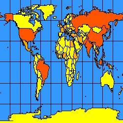
The following two figures show the difference when reaspect is used. The figure on the left has reaspect set to "true". The ENVELOPE is recalculated so that the map does not stretch. The figure on the right has reaspect set to "false", and the map has been stretched to fit the viewing area.
reaspect="true"
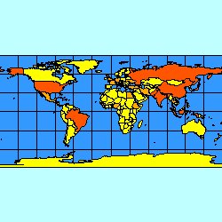
reaspect="false"
- MAPUNITS. MAPUNITS defines the units of the data used in the map. Units are decimal degrees, feet, or meters. If the elements FEATURECOORDSYS and FILTERCOORDSYS are not present, the author of the map configuration file is responsible for determining the MAPUNITS. If MAPUNITS is not included, the assumption is that the MAPUNITS are in decimal degrees. When MAPUNITS is incorrectly specified, measurements, buffers, and other functions using scales will not be correct, and the requested map may not contain any data. If FEATURECOORDSYS and FILTERCOORDSYS are present, the correct MAPUNITS is automatically selected by the ArcIMS Spatial Server. In this case, if MAPUNITS is included in the map configuration file, it is ignored.
- FEATURECOORDSYS and FILTERCOORDSYS. FEATURECOORDSYS and FILTERCOORDSYS set the projection of the service. For an overview of the projection elements, see Using Projection Elements.
PROPERTIES and its child elements valid only with Image Services (in bold)
|
<PROPERTIES> <ENVELOPE minx="-105.594842" miny="-49.955227" maxx="75.672764" maxy="83.596039" name="Initial_Extent" /> <MAPUNITS units="decimal_degrees" /> <FEATURECOORDSYS id="4326" /> <FILTERCOORDSYS id="4326" /> <BACKGROUND... /> <LEGEND... /> <OUTPUT... /> </PROPERTIES> |
- BACKGROUND. BACKGROUND defines a color for the image background. It can also be used to make one color in the image transparent. Depending on the browser, the image formats that support transparent colors vary. JPG images do not support transparent colors. The table below lists which image formats support transparent colors for different browsers.
Browser Supported Transparent Image Formats ArcIMS HTML Viewer in Internet Explorer 6 or higher PNG8, GIF ArcIMS HTML Viewer in Firefox PNG8, PNG24, GIF ArcExplorer PNG8, PNG24, GIF ArcIMS Java Viewers in Internet Explorer and Firefox PNG8, PNG24, GIF
To make a color transparent, both the color and transcolor attributes of BACKGROUND must be set to the same color. When a color is set to transparent, layers underneath the transparent part of the image can be seen.
When the ArcIMS HTML Viewer is used, BACKGROUND added to an Image Service is overridden by BACKGROUND in requests from the HTML Viewer. When the ArcIMS Java Viewers and ArcExplorer are used, the BACKGROUND in the service is not overridden.
- LEGEND. LEGEND defines a map's legend for an Image Service. This legend is valid only in customized ArcIMS HTML Viewers and not in the ArcIMS Java Viewers or ArcExplorer. When LEGEND is included in the map configuration file, a legend image is always generated. However, this legend is ignored by the ArcIMS HTML Viewer. The HTML Viewer generates a legend upon request and ignores any other generated legends. For more information on using LEGEND, see the Using LEGEND and Draw Section in Using GET_IMAGE and IMAGE.
- OUTPUT. OUTPUT defines a location and filename for the output maps and legend image files. In general, it is not recommended to use OUTPUT in a map configuration file unless all requests can use the same output map or legend. Instead, if OUTPUT is needed, it should be used in GET_IMAGE and GET_EXTRACT requests. During a request, more information is known about the requesting client, and the output location and name can be tailored for that client. For more details on using OUTPUT, see the Using OUTPUT to Control Image Name and Locations Section in Using GET_IMAGE and IMAGE with Image Services.
MAP: WORKSPACES
WORKSPACES specifies the location of all the data used in the map configuration file. All data locations must be visible to any computer hosting ArcIMS services. Each workspace must have a unique reference name. Valid WORKSPACES in map configuration files are:- SHAPEWORKSPACE. Used to reference directories with shapefiles.
- IMAGEWORKSPACE. Used to reference directories with images. Images can be accessed individually, as an image directory where all images in one directory can be tiled, or as image catalogs. A complete list of supported images is found in ArcIMS Help.
- SDEWORKSPACE. Used to reference layers in ArcSDE. The layers can be raster or vector layers. Either ArcSDE or ArcSDE Direct Connect can be used.
|
<WORKSPACES> <SHAPEWORKSPACE name="shp_ws-0" directory="c:\ESRIDATA"/> <IMAGEWORKSPACE name="jai_ws-1" directory="c:\ESRIDATA"/> <SDEWORKSPACE name="sde_ws-2" server="myserver" instance="port:5150" database="" user="washoe" encrypted="true" password="LXEMUR" /> </WORKSPACES> |
MAP: LAYER
LAYER is the parent element for defining a map layer. Attributes cannot be overridden by a request. The following attributes are required:- Id is a unique ID for a layer. When using ArcIMS Author, layers are assigned a number. However, the ID can be any combination of alpha and numeric characters. Each layer must have a unique ID or an error will result when trying to start an ArcIMS service.
- Type specifies layer type. Use "featureclass" for shapefiles and ArcSDE vector layers. Use "image" for raster image files, GRIDs, and ArcSDE raster layers. Use "acetate" for adding graphics on top of the map.
- Name is used for the layer name displayed in the legend in all ArcIMS Viewers. If name is not included, the ArcIMS Java Viewers use the LAYER ID, and the HTML Viewer displays a blank name. It is highly recommended to always use name.
- Maxscale and minscale are used to set the maximum and minimum scales that the layer displays. A relative scale can be used, such as 1:24000, or the scale can be calculated as the number of map units per pixel. The method for calculating units per pixel is shown with the LAYER element information. If these attributes are not used, the layer displays at all scales.
Applying maximum and minimum scales to a layer is a very important part of authoring map configuration files. The user should only see data that is relevant and useful at any given scale. If a layer has very detailed information, then this layer should not be available until the user has zoomed in to an appropriate level. The less data that must be accessed and rendered, the faster the map is drawn or data is transferred. A general guideline is that a map should contain no more than 500 or so features at a given scale. In some cases, there may be more features, but realize that the amount of time to generate the map increases, especially when a map is projected.
- Visible specifies whether the layer is turned on or off when the map is first accessed. If the ArcIMS Java Custom Viewer is used, selecting which layers are visible is done during the ArcIMS Designer process. This overrides visible in the ArcIMS service. All other ArcIMS Viewers read visible directly from the service.
|
<LAYER type="featureclass" name="CITIES" minscale="1:24000" maxscale="1:100000" visible="true" id="2"> ... </LAYER> |
MAP: LAYER child elements
A LAYER used in a map configuration file has several child elements. The purpose of these elements is to identify the data source and to render the data.LAYER with child elements
|
<LAYER type="featureclass" name="CITIES" minscale="1:24000" maxscale="1:100000" visible="true" id="2"> <DATASET name="Cities_Robinson" type="polygon" workspace="shp_ws-0" /> <DENSIFY tolerance="10000" /> <COORDSYS id="54030" /> <SPATIALQUERY where="population > 1000000" /> <SIMPLERENDERER> <SIMPLEPOLYGONSYMBOL filltransparency="1.0" fillcolor="27,127,127" /> </SIMPLERENDERER> </LAYER> |
The types of child elements can be divided into several groups: DATASET, projection elements, query elements, EXTENSION elements, and renderer and symbol elements.
- DATASET is required for a layer. It defines which data from a workspace to use. Information in DATASET cannot be overridden by a request.
The attribute name is required. For shapefiles, use the name of the data file without an extension such as STATES. For ArcSDE, use the full name of the layer such as DATA.STATES. For images, the name depends on the method for accessing an image. For more details on naming images, see the table in the Notes section in DATASET.
The attribute type is required for vector data and optional for image data. The value for type must match the shapefile or ArcSDE layer type: "point", "line", or "polygon". For images, always use the value "image".
The attribute workspace is required and references which workspace the data layer is in. The workspace value must be listed under WORKSPACES.
- The projection elements COORDSYS and DENSIFY are used if the data layer is in a different projection than the ArcIMS service. These elements are metadata stating what projection the layer is in, but they do not reproject the data. For more information on the projection elements, see Using the Projection Elements.
- The query elements SPATIALQUERY and QUERY are used to select a subset of the layer. SPATIALQUERY should be used for both tabular and spatial queries. QUERY should only be used in stored queries.
When SPATIALQUERY is used with a layer in a map configuration file, a filter is set on a subset of the data and only that subset is available for viewing. When a request is made with SPATIALQUERY, the data outside of the ArcIMS service subset cannot be accessed.
- The EXTENSION element is used to define geocoding, stored queries, and extract parameters for a layer. All three extensions can be used for a single layer, but each EXTENSION can only have one set of child elements.
For geocoding, use GCSTYLE. This extension sets up the type of geocoding used on the layer. More information on geocoding is available in Summary of Geocoding Elements.
For setting up parameters for the Extract Server, use EXTRACTPARAMS. Using this extension allows HTML clients to send requests that extract specified layers of an ArcIMS service into a set of shapefiles, yielding one shapefile for each layer. More information on the Extract EXTENSION is available in Using GET_EXTRACT and EXTRACT.
For setting up a stored query, use STOREDQUERIES. A stored query sets up a predefined query used in the ArcIMS Viewers.
- The renderer and symbol elements are used to define the symbology and labeling for each layer in the map. The relationship between a renderer and a symbol in ArcXML is
<RENDERER>
<SYMBOL />
</RENDERER>
The following renderers are available in ArcIMS:
- RASTER_RENDERER
- SIMPLERENDERER
- SIMPLELABELRENDERER
- VALUEMAPRENDERER
- VALUEMAPLABELRENDERER
- GROUPRENDERER
- SCALEDEPENDENTRENDERER
Note: RASTER_RENDERER is valid only on image layers and can be specified only in map configuration files. For more information on RASTER_RENDERER and its child elements, see RASTER_RENDERER.
VALUEMAPRENDERER and VALUEMAPLABELRENDERER have three child elements used to create value maps:
Only one symbol or label at a time can be used inside a renderer. However, the renderers can be used in different combinations to create complex symbols at different scales.
Valid symbols inside SIMPLERENDERER and VALUEMAPRENDERER are:- Point layers
- Line layers
- All the symbols valid for point layers
- HASHLINESYMBOL
- SIMPLELINESYMBOL
- Polygon layers
- All the symbols valid for point and line layers
- GRADIENTFILLSYMBOL
- RASTERFILLSYMBOL
- SIMPLEPOLYGONSYMBOL
Valid symbols inside SIMPLELABELRENDERER and VALUEMAPLABELRENDERER are:
For more detailed information on the renderers, see Using Renderer Elements.
Sample map configuration file
The following map configuration file uses many of the elements discussed above.Example map configuration file
|
<?xml version="1.0" encoding="UTF-8"?> <ARCXML version="1.1"> <CONFIG> <ENVIRONMENT> <LOCALE country="US" language="en" variant="" /> <UIFONT color="0,0,0" name="Arial" size="12" style="regular" /> <SCREEN dpi="96" /> </ENVIRONMENT> <MAP> <PROPERTIES> <ENVELOPE minx="-135.0" miny="-64.0" maxx="84.0" maxy="86.0" name="Initial_Extent" /> <MAPUNITS units="decimal_degrees" /> <FILTERCOORDSYS id="4326" /> <FEATURECOORDSYS id="4326"/> </PROPERTIES> <WORKSPACES> <SHAPEWORKSPACE name="shp_ws-4" directory="<path to WORLD ESRIDATA>" /> </WORKSPACES> <LAYER type="featureclass" name="Oceans" visible="true" id="0"> <DATASET name="WORLD30" type="polygon" workspace="shp_ws-4" /> <SIMPLERENDERER> <SIMPLEPOLYGONSYMBOL fillcolor="51,153,255"/> </SIMPLERENDERER> </LAYER> <LAYER type="featureclass" name="Countries" visible="true" id="1"> <DATASET name="country" type="polygon" workspace="shp_ws-4" /> <GROUPRENDERER> <VALUEMAPRENDERER lookupfield="POP_CNTRY"> <RANGE lower="0" upper="50000000" label="Less than 50000000"> <SIMPLEPOLYGONSYMBOL fillcolor="255,255,0"/> </RANGE> <RANGE lower="50000001" upper="100000000" label="50000000 - 100000000"> <SIMPLEPOLYGONSYMBOL fillcolor="255,170,0" /> </RANGE> <RANGE lower="100000001" upper="1281008319" label="Greater than 100000000"> <SIMPLEPOLYGONSYMBOL fillcolor="255,85,0"/> </RANGE> </VALUEMAPRENDERER> <SCALEDEPENDENTRENDERER upper="1:35000000"> <SIMPLELABELRENDERER field="CNTRY_NAME"> <TEXTSYMBOL antialiasing="true" font="Arial Bold" fontstyle="bold" fontsize="12" /> </SIMPLELABELRENDERER> </SCALEDEPENDENTRENDERER> </GROUPRENDERER> </LAYER> </MAP> </CONFIG> </ARCXML> |
The map configuration file contains information on the locale, map properties, workspaces, and how each layer should be drawn. In the ENVIRONMENT section, the LOCALE country and language are the "US" and "En". For UIFONT, the default font of Arial is used, and the default dpi in SCREEN is 96. The PROPERTIES elements show that the MAPUNITS are in decimal degrees and the ENVELOPE coordinates are -135.0 -64.0 and 84.0 86.0. In the WORKSPACES section, one SHAPEWORKSPACE is included for shapefiles in the WORLD ESRIDATA dataset.
The map contains two layers:
- Ocean. This layer contains one renderer, SIMPLERENDERER. The layer has a solid blue fill as described in SIMPLEPOLYGONSYMBOL.
- Countries. This layer contains several renderers. A VALUEMAPRENDERER is used to define how each country should be colored based on population. Countries with a population less than 50 million are yellow, those with a population between 50 and 100 million are light orange, and those with a population greater than 100 million are dark orange. A SCALEDEPENDENTRENDERER is used for labeling. The labels do not turn on until the scale is less than 1:35000000.

|
|
If the initial extent is changed so the scale is less than 1:35000000, the map zooms in enough so that labels for countries appear.
Change in initial ENVELOPE
|
<?xml version="1.0" encoding="UTF-8"?> <ARCXML version="1.1"> <CONFIG> <ENVIRONMENT>...</ENVIRONMENT> <MAP> <PROPERTIES> <ENVELOPE minx="-13.0" miny="36.0" maxx="34.0" maxy="69.0" name="Initial_Extent" /> <MAPUNITS units="decimal_degrees" /> <FILTERCOORDSYS id="4326" /> <FEATURECOORDSYS id="4326"/> </PROPERTIES> <WORKSPACES>...</WORKSPACES> <LAYER>...</LAYER> </MAP> </CONFIG> </ARCXML> |
The following figure shows a map at a scale of about 1:35000000 and includes labels.
|
|
|
Viewer Configuration Files
Viewer configuration files are the output when a file is saved in ArcExplorer or the ArcIMS Java Viewers and reside on the local machine. The diagram below provides a more detailed flow of the process to create a viewer configuration file:
|
- In Step 1, ArcIMS services and local data sources are accessed and viewed in ArcExplorer or an ArcIMS Java Viewer.
- In Step 2, when a session is saved, the output is a viewer configuration file.
Framework of a viewer configuration file
The framework of a viewer configuration file is similar to a map configuration file. The framework includes the CONFIG, ENVIRONMENT, and MAP elements. These elements function the same in both map and viewer configuration files. PROPERTIES is fundamentally the same as well, but only ENVELOPE and MAPUNITS are included.In many cases, a viewer configuration file can look just like a map configuration file. This is true when only local data sources are included in the file and the only WORKSPACES present are SHAPEWORKSPACE, IMAGEWORKSPACE, and SDEWORKSPACE.
Viewer configuration files can contain additional elements that are not in a map configuration file. The following example shows some of these elements.
Example viewer configuration file
|
<?xml version="1.0" encoding="UTF-8"?> <ARCXML version="1.1"> <CONFIG> <ENVIRONMENT> <LOCALE country="US" language="en" variant="" /> <UIFONT color="0,0,0" name="Arial" size="12" style="regular" /> <SCREEN dpi="96" /> </ENVIRONMENT> <MAP> <PROPERTIES> <ENVELOPE minx="-178.0" miny="12.89" maxx="-68.0" maxy="83.59" name="Initial_Extent" /> <MAPUNITS units="decimal_degrees" /> </PROPERTIES> <WORKSPACES> <IMAGESERVERWORKSPACE name="mapper_ws-6" url="http://mymachine.domain.com/servlet/com.esri.esrimap.Esrimap" service="background" /> <FEATURESERVERWORKSPACE name="ifs_ws-7" url="http://mymachine.domain.com/servlet/com.esri.esrimap.Esrimap" service="states" /> <SHAPEWORKSPACE name="shp_ws-8" directory="<path to CANADA ESRIDATA" /> </WORKSPACES> <LAYER type="image" name="Background" visible="true" id="0"> <DATASET name="background" type="image" workspace="mapper_ws-6" /> </LAYER> <LAYER type="featureclass" name="States" visible="true" id="1"> <DATASET name="2" type="polygon" workspace="ifs_ws-7" /> <SIMPLERENDERER> <SIMPLEPOLYGONSYMBOL boundarytransparency="1.0" filltransparency="1.0" fillcolor="255,255,153" boundarycaptype="round" /> </SIMPLERENDERER> </LAYER> <LAYER type="featureclass" name="Provinces" visible="true" id="2"> <DATASET name="province" type="polygon" workspace="shp_ws-8" /> <SIMPLERENDERER> <SIMPLEPOLYGONSYMBOL boundarytransparency="1.0" filltransparency="1.0" fillcolor="127,27,27" boundarycaptype="round" /> </SIMPLERENDERER> </LAYER> <LAYER type="image" name="Roads" visible="true" id="3"> <DATASET name="mymachine.domain.com:roads21204240:Roads" type="image" workspace="av_ws-6" /> <IMAGEPROPERTIES transparency="0.80" /> </LAYER> <LAYER type="image" name="GPS Points" visible="true" id="4"> <DATASET name="mymachine.domain.com:GPS_Points" type="image" workspace="mo_ws-4" /> </LAYER> </MAP> <OVERVIEWMAP backgroundcolor="255,255,255" framefillcolor="255,0,0,80" frameoutlinecolor="255,0,0" zoomfactor="4.0"> <LAYERDEF name="States" /> <LAYERDEF name="Provinces" /> </OVERVIEWMAP> <SCALEBAR backcolor="212,208,200" fontcolor="0,0,0" mapunits="decimal_degrees" scaleunits="feet" screenunits="inches" /> </CONFIG> </ARCXML> |
The additional elements are:
- IMAGESERVERWORKSPACE. IMAGESERVERWORKSPACE is included in the WORKSPACES section when an Image Service is accessed.
- FEATURESERVERWORKSPACE. FEATURESERVERWORKSPACE is included in the WORKSPACES section when a Feature Service is accessed.
- SCALEBAR and OVERVIEWMAP. These two elements are client configuration elements that add a scale bar or overview map, respectively.
IMAGESERVERWORKSPACE
IMAGESERVERWORKSPACE is used in the WORKSPACES section for Image Service layers.Using IMAGESERVERWORKSPACE
|
<?xml version="1.0" encoding="UTF-8"?> <ARCXML version="1.1"> <CONFIG> <ENVIRONMENT>...</ENVIRONMENT> <MAP> <PROPERTIES>...</PROPERTIES> <WORKSPACES> <IMAGESERVERWORKSPACE name="mapper_ws-6" url="http://mymachine.domain.com/servlet/com.esri.esrimap.Esrimap" service="background" /> </WORKSPACES> <LAYER type="image" name="Background" visible="true" id="0"> <DATASET name="background" type="image" workspace="mapper_ws-6" /> </LAYER> </MAP> <OVERVIEWMAP>...</OVERVIEWMAP> <SCALEBAR ... /> </CONFIG> </ARCXML> |
References to an Image Service in IMAGESERVERWORKSPACE are made in the service attribute. In the above example, the name of the Image Service is "background". The url attribute gives the location of the Image Service. In the example, the location is "http://mymachine.domain.com". In addition to the domain, the location of the ArcIMS Servlet Connector is also included. This information is the same for all ArcIMS sites and is "/servlet/com.esri.esrimap.Esrimap".
For the Image Service layer, references to the ArcIMS service are made in DATASET. The attribute name is the same as IMAGESERVERWORKSPACE service. In this example, the name is "background". The DATASET type is always "image". Image Service layers are always treated as one layer in a viewer configuration file.
FEATURESERVERWORKSPACE
FEATURESERVERWORKSPACE is used in the WORKSPACES section for Feature Service layers.Using FEATURESERVERWORKSPACE
|
<?xml version="1.0" encoding="UTF-8"?> <ARCXML version="1.1"> <CONFIG> <ENVIRONMENT>...</ENVIRONMENT> <MAP> <PROPERTIES>...</PROPERTIES> <WORKSPACES> <FEATURESERVERWORKSPACE name="ifs_ws-7" url="http://mymachine.domain.com/servlet/com.esri.esrimap.Esrimap" service="states" /> </WORKSPACES> <LAYER type="featureclass" name="States" visible="true" id="1"> <DATASET name="3" type="polygon" workspace="ifs_ws-7" /> <SIMPLERENDERER> <SIMPLEPOLYGONSYMBOL boundarytransparency="1.0" filltransparency="1.0" fillcolor="255,255,153" boundarycaptype="round" /> </SIMPLERENDERER> </LAYER> </MAP> <OVERVIEWMAP>...</OVERVIEWMAP> <SCALEBAR ... /> </CONFIG> </ARCXML> |
References to a Feature Service in FEATURESERVERWORKSPACE are made in the service attribute. In the above example, the name of the Feature Service is "States". The url attribute is used the same way as with Image Service. In the example, the location of the ArcIMS Servlet Connector is "http://mymachine.domain.com/servlet/com.esri.esrimap.Esrimap".
Each layer in a Feature Service is treated as a separate layer, and each layer can be accessed individually. In the above example, only one layer of a Feature Service has been accessed.
For a Feature Service layer, DATASET is always included, and rendering information is usually included. In DATASET, the attribute type is set to the same type as in the Feature Service. In the above example the type is "polygon". The attribute name is set to the LAYER id in the Feature Service. In this example, the LAYER id in the Feature Service is "3"; therefore, the DATASET name in the viewer configuration file is "3". The following examples highlight the differences between the map configuration file used as input to the Feature Service and the output in the viewer configuration file.
Map configuration file used in the Feature Service
|
<LAYER type="featureclass" name="States" visible="true" id="3"> <DATASET name="STATES" type="polygon" workspace="shp_ws-1" /> <SIMPLERENDERER> <SIMPLEPOLYGONSYMBOL boundarytransparency="1.0" filltransparency="1.0" fillcolor="255,255,153" boundarycaptype="round" /> </SIMPLERENDERER> </LAYER> |
Viewer configuration file
|
<LAYER type="featureclass" name="States" visible="true" id="1"> <DATASET name="3" type="polygon" workspace="ifs_ws-7" /> <SIMPLERENDERER> <SIMPLEPOLYGONSYMBOL boundarytransparency="1.0" filltransparency="1.0" fillcolor="255,255,153" boundarycaptype="round" /> </SIMPLERENDERER> </LAYER> |
In the map configuration file, the LAYER id is "3", which is unique within the map configuration file, and the DATASET name is "STATES" and refers to a shapefile in the "shp_ws-1" workspace. In the viewer configuration file, the LAYER id is "1", which is unique within the viewer configuration file. The DATASET name is "3", which refers to the LAYER id in the map configuration file. The workspace reference is "ifs_ws-7", which refers to the workspace for the Feature Service. The rest of the layer information in the map and viewer configuration files is identical.
When using ArcExplorer and when permission is given in the ArcIMS Java Viewers, the layer rendering can be changed using the viewer's Layer Properties Dialog. In the following example, the States layer starts off rendered in light yellow.
Default viewer configuration file
|
<LAYER type="featureclass" name="States" visible="true" id="1"> <DATASET name="2" type="polygon" workspace="ifs_ws-7" /> <SIMPLERENDERER> <SIMPLEPOLYGONSYMBOL boundarytransparency="1.0" filltransparency="1.0" fillcolor="255,255,153" boundarycaptype="round" /> </SIMPLERENDERER> </LAYER> |
|
If a user changes the rendering, this new information is stored in the viewer configuration file. The change is local and does not affect the Feature Service. In the next example, the rendering is changed from light yellow to various colors based on the population of each state.
After layer rendering has been changed in the viewer configuration file
|
<LAYER type="featureclass" name="States" visible="true" id="1"> <DATASET name="2" type="polygon" workspace="ifs_ws-7" /> <VALUEMAPRENDERER lookupfield="POP1999"> <RANGE lower="482025" upper="11351422" label="Less than 11351422"> <SIMPLEPOLYGONSYMBOL boundarytransparency="1.0" filltransparency="1.0" fillcolor="255,255,0" boundarycaptype="round" /> </RANGE> <RANGE lower="11351422" upper="22220818" label="11351422 - 22220818"> <SIMPLEPOLYGONSYMBOL boundarytransparency="1.0" filltransparency="1.0" fillcolor="255,170,0" boundarycaptype="round" /> </RANGE> <RANGE lower="22220818" upper="33090215" label="22220818 - 33090215"> <SIMPLEPOLYGONSYMBOL boundarytransparency="1.0" filltransparency="1.0" fillcolor="255,85,0" boundarycaptype="round" /> </RANGE> </VALUEMAPRENDERER> </LAYER> |
|
Remember that in a viewer configuration file, any rendering changes remain local to the machine that the configuration file resides on. The change does not affect the Feature Service.
SHAPEWORKSPACE, IMAGEWORKSPACE, and SDEWORKSPACE
SHAPEWORKSPACE, IMAGEWORKSPACE, and SDEWORKSPACE are used when local data is referenced in the viewer configuration file. These WORKSPACES elements reference data exactly the same way as in a map configuration file.OVERVIEWMAP and SCALEBAR
OVERVIEWMAP and SCALEBAR are client configuration elements and add an overview map or scale bar, respectively.
|
Both elements are saved when using ArcExplorer or an ArcIMS Java Standard Viewer. Only SCALEBAR is saved in an ArcIMS Java Custom Viewer even if an overview map is present. Also, the ArcIMS Java Custom Viewer ignores these elements when a viewer configuration file is read into the viewer.
Using OVERVIEWMAP and SCALEBAR
|
<?xml version="1.0" encoding="UTF-8"?> <ARCXML version="1.1"> <CONFIG> <ENVIRONMENT>...</ENVIRONMENT> <MAP>...</MAP> <OVERVIEWMAP backgroundcolor="255,255,255" framefillcolor="255,0,0,80" frameoutlinecolor="255,0,0" zoomfactor="4.0"> <LAYERDEF name="Oceans" /> <LAYERDEF name="Countries" /> </OVERVIEWMAP> <SCALEBAR backcolor="212,208,200" fontcolor="0,0,0" mapunits="decimal_degrees" scaleunits="feet" screenunits="inches" /> </CONFIG> </ARCXML> |
Default.axl: A Special Viewer Configuration File
Default.axl is a special viewer configuration file that is output by ArcIMS Designer when an ArcIMS Java Viewer is created. The diagram below shows the process to create default.axl:
|
- In Step 1, one or more ArcIMS services are selected during the ArcIMS Designer process.
- In Step 2, when a Web site is generated, one of the output files in the directory is default.axl.
- In Step 3, when an ArcIMS Java Standard or Java Custom Viewer is opened, default.axl is loaded in the viewer. The file contains information on which services should be loaded in the viewer.
Framework of default.axl
Default.axl uses a subset of elements normally found in a viewer configuration file. Its primary purpose is to load ArcIMS service layers specified during the ArcIMS Designer process.Example default.axl file
|
<?xml version="1.0" encoding="UTF-8"?> <ARCXML version="1.1"> <CONFIG> <MAP> <PROPERTIES> <ENVELOPE minx="-180.0" miny="-90.0" maxx="180.0" maxy="90.0" name="Initial_Extent" /> <MAPUNITS units="decimal_degrees" /> </PROPERTIES> <WORKSPACES> <IMAGESERVERWORKSPACE name="mapper_ws-6" url="http://mycomputer.domain.com/servlet/com.esri.esrimap.Esrimap" service="background" /> <FEATURESERVERWORKSPACE name="ifs_ws-7" url="http://mycomputer.domain.com/servlet/com.esri.esrimap.Esrimap" service="World" /> </WORKSPACES> <LAYER type="image" name="background" visible="true" id="0"> <DATASET name="background" type="image" workspace="mapper_ws-6" /> </LAYER> <LAYER type="featureclass" name="Countries" visible="true" id="1"> <DATASET name="0" type="polygon" workspace="ifs_ws-7" /> </LAYER> <LAYER type="featureclass" name="United States" visible="true" id="2"> <DATASET name="1" type="polygon" workspace="ifs_ws-7" /> </LAYER> </MAP> <SCALEBAR backcolor="212,208,200" fontcolor="0,0,0" mapunits="decimal_degrees" scaleunits="feet" screenunits="inches" /> </CONFIG> </ARCXML> |
Only elements that are needed to load the ArcIMS services are included. The principal similarities and differences between default.axl and a viewer configuration file are:
- CONFIG and MAP. These elements are always present in a configuration file.
- ENVIRONMENT. The ENVIRONMENT elements are not included in default.axl. Since the information on locale is already associated with the ArcIMS services, the ENVIRONMENT information does not need to be duplicated in default.axl.
- WORKSPACE elements. FEATURESERVERWORKSPACE and IMAGESERVERWORKSPACE are added during the ArcIMS Designer process.
- PROPERTIES. This section is the same as for viewer configuration files. The one exception is the use of ENVELOPE. In the Java Custom Viewer, two ENVELOPE elements may be included. If only one ENVELOPE is included, only the initial extent for the map is included. The following figure shows the initial extent of a world map when the following ENVELOPE is used:
Using ENVELOPE Initial_Extent<PROPERTIES>
<ENVELOPE minx="-180.0" miny="-90.0" maxx="180.0" maxy="90.0" name="Initial_Extent"/>
<MAPUNITS units="decimal_degrees" />
<PROPERTIES>
If two ENVELOPE elements are included, the first is the map’s initial extent, and the second is the maximum zoom limit of the map. These extents are set during the ArcIMS Designer process. The coordinates used in the extent limit represent the maximum limit of data that can be shown. In the next example, the initial extent and the extent limit are set to an envelope that bounds the United States, although a world dataset was used. In the Java Custom Viewer, only the region inside the extent limit displays.
Using ENVELOPE Initial_Extent and Extent_Limit<PROPERTIES>
<ENVELOPE minx="-61.1" miny="3.7" maxx="91.7" maxy="61.3" name="Initial_Extent"/>
<ENVELOPE minx="-61.1" miny="3.7" maxx="91.7" maxy="61.3" name="Extent_Limit"/>
<MAPUNITS units="decimal_degrees" />
<PROPERTIES>
- LAYER and DATASET. The rules for assigning attribute values are the same as for viewer configuration files. However, no rendering information is included with the layer.
- SCALEBAR. SCALEBAR is always included in default.axl with Java Standard Viewer Web sites but not with Java Custom Viewer web sites.
Including SCALEBAR<?xml version="1.0" encoding="UTF-8"?>
<ARCXML version="1.1">
<CONFIG>
<MAP>...</MAP>
<SCALEBAR backcolor="212,208,200" fontcolor="0,0,0" mapunits="decimal_degrees" scaleunits="feet" screenunits="inches" />
</CONFIG>
</ARCXML>
- OVERVIEWMAP. OVERVIEWMAP is not included in default.axl.
Relationship between Feature Services and default.axl
When ArcIMS Designer creates default.axl and a Feature Service is included, one LAYER is included in default.axl for every LAYER in the Feature Service. Since no rendering is included in default.axl, the rendering defined in the ArcIMS service is what is used by the ArcIMS Java Viewers. Any changes to the rendering in the service are immediately reflected in the ArcIMS Java Viewers.Caution is needed when adding or deleting layers in Feature Service. If a layer is added to a service but not to default.axl, the ArcIMS Java Viewer will not display the new layer. If a layer is deleted from a service but not default.axl, an error message appears in the ArcIMS Java Viewer because a layer referenced in default.axl cannot be found in the service. In summary, if a layer is added or deleted in a service, it should be added or deleted in default.axl.
Comparing Different CONFIG Files
The table below summarizes the similarities and differences between map configuration files, viewer configuration files, and default.axl.| Map Config | Viewer Config | Default.axl | |
|---|---|---|---|
| Primary purpose | Used as input to ArcIMS services | Saves current map and viewer configuration on the client | Used to load ArcIMS services in an ArcIMS Java Viewer |
| Created by | ArcIMS Author or XML Editor | ArcExplorer or ArcIMS Java Viewers | ArcIMS Designer |
| File is located | On server | On client | On server |
| Data sources | Local network only and must be accessible by ArcIMS Spatial Server | ArcIMS services and local network on client | ArcIMS services only |
| Valid workspaces | SHAPEWORKSPACE, IMAGEWORKSPACE, SDEWORKSPACE | IMAGESERVERWORKSPACE, FEATURESERVERWORKSPACE, SHAPEWORKSPACE, IMAGEWORKSPACE, SDEWORKSPACE | IMAGESERVERWORKSPACE, FEATURESERVERWORKSPACE |